Holcroft's Cylinder and Crankpin Offset Modification Formula
Updated: 3/18/2024
Updated: 3/18/2024
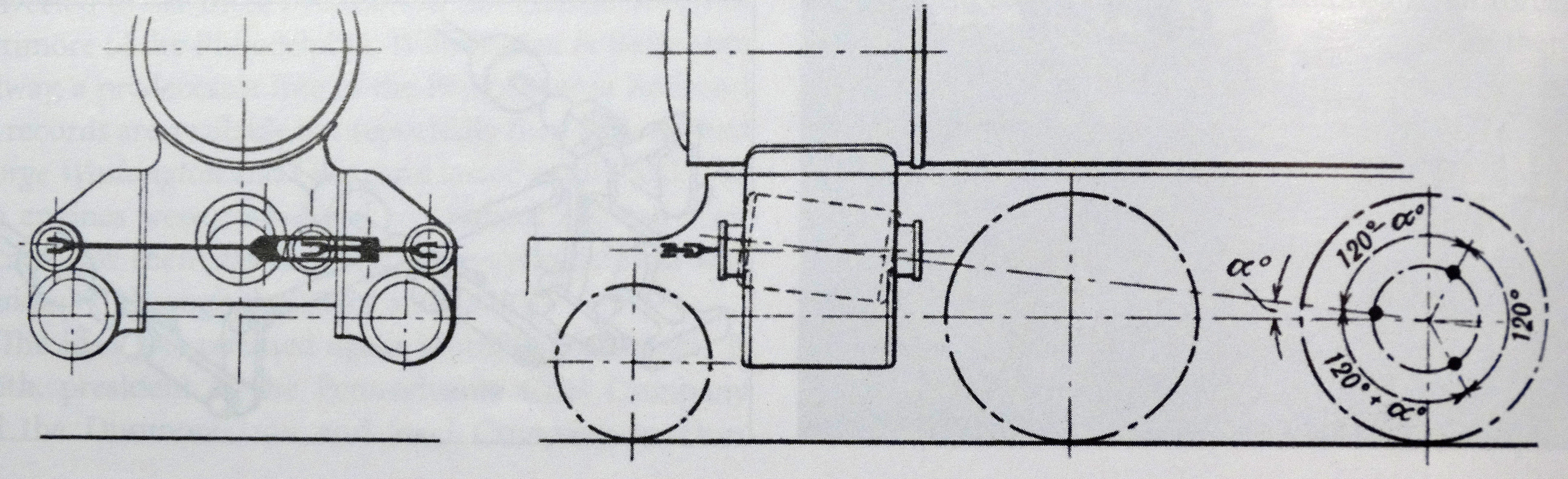
When designing engines with both inside and outside cylinders in which you want to attach the inside connecting rods to an axle other than the first, you will need to set the inside cylinders at an angle out of line with the horizontal cylinders to give clearance for the first axle. The corresponding crank pins should also be offset, to maintain the smoothest possible flow of torque. This trait is found in most 3 cylinder locomotives.
First, set all of the cylinders inline and the crank pins in the desired configuration. Move the cylinder to be inclined to top dead center. Then incline the cylinder and corresponding crank pin at coterminal and equal angles, the vertex being at the center of the crank axle, while keeping the positions of the outside cylinders and crank pins fixed. Repeat this process until all of the inside cylinders have been inclined.
This works because although the angle of the piston has changed, the equivalent alteration of the crankpin position ensures the phase of the piston head is normalized for any given crank axle position. What ultimately matters for having the smoothest flow of torque is the phase of the piston rather than the angle of the piston or crank pins. For Example: If you properly offset the middle cylinder and crankpin of a three cylinder locomotive, with inline cranks at 0°, 120°, and 240°, the phases of the piston heads remain at 0°, 120°, and 240°. Thus the phases of the piston valves do not change. Thus this does not necessitate changing any other function altering dimensions in the engine or the outside valve gear, and will not be accounted for in the conjugated lever polar deriving process.